
✅ What we know
- Many mobile-repair / data‐recovery posts refer to performing “ISP” (In-System Programming) on BGA-254 eMCP chips. For example: “direct ISP pinout” for BGA254 is mentioned in tutorials.
- One forum thread explains that for BGA254 the ISP process is more difficult (cable length, correct VCC/VCCQ, etc).
- There are adapter products specifically marketed for BGA-254 (“uMCP-BGA-254” support) showing that the pinout is distinct and adapter layouts exist.
⚠️ Important caveats
- I did not find a publicly available, fully detailed and reliable official pin-by-pin diagram showing every signal for BGA-254.
- Many of the diagrams found are in grey forums, image blogs, or require registration, which may be unreliable.
- ISP for eMCP/eMMC often involves bypassing or hooking into test-points/traces on the phone motherboard, so the “pinout” may vary depending on board/design.
- Errors in connection (wrong VCC, VCCQ, long jumpers) can result in failure or damage. As per one discussion: “just do ‘Identify eMMC’ … select BGA 254 to see the connection pinout there”
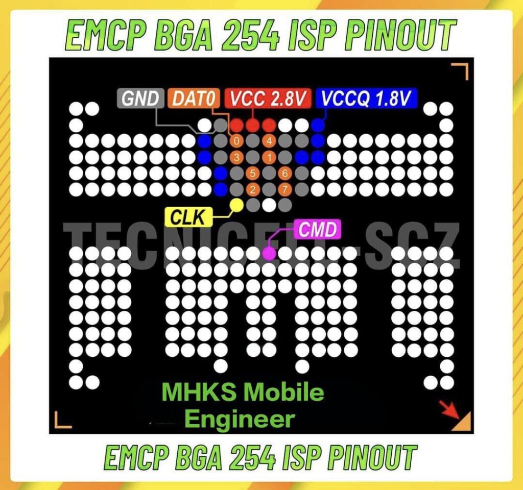
🔍 Typical signals you’ll need to connect
When doing an ISP on an eMCP/eMMC chip, you typically need access to:
- VCC (power supply for the eMMC core)
- VCCQ (I/O supply)
- GND (ground)
- CLK (clock)
- CMD (command line)
- DATA0-DATA7 (data bus lines) — depending on bus width
- Sometimes RST_n or /RST (reset) or /EN lines
- Possibly BOOT1/BOOT2, RPMB lines or other partitions depending on chip configuration
Tutorials mention these specifically for “BGA254 eMMC & eMCP ISP”:
🛠 Example connection / adapter hints
From forum posts:
- Keep jumper wires as short as possible.
- For BGA254 with active PBL (Pre-Boot Loader) you may need to bypass VCC/VCCQ and use USB power instead.
- One blog lists “BGA 254 Direct ISP Pinout” entry under its heading (though without full public disclosure of all pins)
- Many complaints of “it doesn’t work” because either wrong adapter, wrong pinout selection in software tools, or mounting issues for BGA254.
📎 What you should do if you intend to use it
- Use a verified adapter designed for BGA-254 eMCP / eMMC.
- In your ISP software/hardware tool choose the option or profile “BGA 254”. Many tools show this as pre-set.
- Visually inspect the chip package, find the orientation (often a triangle or dot indicates “Pin 1”) and trace the test points on the board.
- Measure VCC and VCCQ on the board before attaching jumpers.
- Short jumpers, good grounding, clean soldering are essential.
- Be aware that even with correct pinout, success depends on board design, security features, and firmware.
If you like, I can search for and send you a detailed high-resolution pinout diagram (e.g., PDF or image) specific for one major chip vendor’s eMCP BGA-254 (Samsung, Micron, etc.) so you can see every ball/test-point mapping. Would that be helpful?